Optoacoustic Effects
Contents
11. Optoacoustic Effects#
Name:
Total Points: –/100 pts
### UNCOMMENT AND RUN THIS CELL IF USING GOOGLE COLAB
# !pip install ipympl -q
# from google.colab import output
# output.enable_custom_widget_manager()
11.1. Interaction of Acoustic Waves and Optical Waves#
How can light interact with acoustic waves? Well, acoustic waves are just density variations within a material. Since the material polarization (and hence refractive index) is proportional to the number of dipoles per unit volume, a density wave can also lead to a polarization wave.
But this is not the only way that energy can be exchanged between acoustic waves and optical waves. There are a few more:
Photoelastic effect: Also known as the piezo-optic effect. In the photoelastic effect, the strain in the material induces a change in the dielectric constant. This effect applies to materials of all crystal symmetries, and it’s symmetry properties are identical to the third order susceptibility tensor.
Electrostriction: Electrostriction occurs when atoms in a crystal lattice are displaced relative to one another when a field is applied. Positive ions are shifted in one direction, and negative ions in another direction. It varies as the square of the applied field, and the resulting displacements lead to a bulk effect of stress and/or strain within a material.
Piezoelectric and inverse Piezoelectric effect: These are like electrostriction, but only occur in non-centrosymmetric media. Varies linearly with with applied field.
Thermo-optic effects: When a material aborbs light, it heats up and the refractive index changes. If two waves interfere, the refractive index will change more at the anti-nodes, and can set up a refractive index wave.
Boundary Optomechanical Effects: If the dielectric properties change within a material, then acoustic vibrations can lead to changes in the dielectric properties at a particular location.
Note that when we say acoustic waves, we mean waves that are much larger than the interatomic spacing between atoms in a crystal. This is in contrast to the vibrations responsible for Raman scattering, which resulted directly from vibrations occurring at scales close to the lattice spacing. Often the phonons produced by these two length scales are called optical phonons vs. acoustic phonons.
11.2. Frequecy Shifting of Light by Acoustic Waves#
Let’s work out how an ultrasonic wave can induce a nonlinear polarization through electrostriction. We’ll then use that nonlinear polarization in the electric field wave equations to see some nonlinear optical effects.
We start by writing the acoustic wave in the same form as the electric field waves. We’ll let \(Q\) signify the mechanical displacement, \(\Omega_A\) the acoustic angular frequency, and \(K_A\) the acoustic wavenumber:
We have chosen this wave to travel in the \(y\) direction. It is somewhat difficult to measure the amplitude of internal displacements within a material, but often much easier to apply and measure a strain \(S = \partial Q/\partial y\). For this reason, the electrostrictive constant \(\gamma_e\) is given as a measure of the change in the dielectric constant as a function of strain:
The upshot is that we need to write our acoustic wave interms of the strain:
So we conclude that the acoustic wave sets up dielectric constant wave:
If a laser field is incident on this material, it will set up a polarization equal to \(P = \epsilon_0\chi E = \epsilon_0(\delta \epsilon - 1)E\). The nonlinear polarization will therefore be
Writing the electric field of the laser as
we obtain
We can thus see that the effect of the mechanical wave is to produce a polarization wave oscillating at frequencies \(\omega_L \pm \Omega_A\). This is the same process used in acousto-optic modulators and deflectors.
We actually need to generalize our nonliear polarization a bit to account for the fact that the direction of propagation of the light wave does not need to be in the same direction as the acoustic wave. In fact, for most acousto-optic modulators the two direction are perpindicular! We do this by writing the wavenumbers \(k_L\) and \(K_A\) as wave vectors \(\mathbf{k}_L\) and \(\mathbf{K}_A\) and the spatial coordinate \(y\) as a spatial vector \(\mathbf{r}\). Our nonlinear polarization becomes:
Here’s a diagram showing the addition of wave-vectors for a typical acousto-optic modulator:

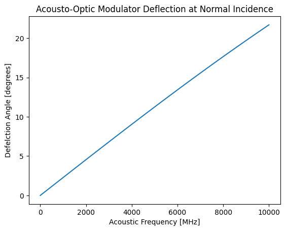
How large of a deflection might we expect to acheive? Let’s calculate:
import numpy as np
from matplotlib import pyplot as plt
lamL = 1e-6
kL = 2*np.pi/lamL

OmegaA = np.linspace(1, 10e9, 100)
vA = 4000 #velocity of acoustic wave
KA = OmegaA/vA


def_angle = np.rad2deg(np.arctan(KA/kL))
plt.plot(OmegaA/1e6, def_angle)
plt.title('Acousto-Optic Modulator Deflection at Normal Incidence')
plt.xlabel('Acoustic Frequency [MHz]')
plt.ylabel('Defelction Angle [degrees]')
plt.show()

So it looks like to get a deflection of more than a few degrees, we need to have an acoustic frequency of > 1 GHz. But what about phase matching?
The wavevector of the generated optical wave along the propogation direction of the laser is \(k_L\cos \theta\), so the wavevector mismatch is
This is typically a very short coherence length (microns), and acousto-optic modulators in which the crystal width is much smaller than the coherence length regime are said to operate in the Raman-Nath regime.
11.3. Exercises#
(50 pts) For a normal incident laser with parameter identical to the calculation above, plot the coherence length as a function of acoustic frequency.
(50 pts) Phase matching can be acheived by angling the acoustic wave so that it is it is not quite perpedincular to the optical wave (see Fig. 5.9 in New). Plot the rotation angle needed for perfect phase matching as a function of acoustic frequency.


